GEA
Enhancing efficiency with a new approach to system design and 3D factory layout
INTEGRATED FACTORY MODELING
Share this story
Global industrial processing systems manufacturer GEA creates 2D and 3D layouts simultaneously using Factory Design Utilities
GEA manufactures large, complex processing systems used in the food, beverage, dairy, pharmaceutical, and chemical industries, among many others. To streamline its most complex work, the company used a special toolset within Autodesk® Inventor® to create custom systems automatically from standard components. Then a member of the engineering team discovered that Autodesk Factory Design Utilities could take them one step further and reduce the amount of time involved by 80%.

Cupcake injector equipment built by GEA. Image courtesy of GEA.
Keeping the world moving
If you’ve ever wondered how the filling gets inside a cupcake or how frosted cereal flakes get that way, the answer can be found in the vast product portfolio of Dusseldorf, Germany-based GEA.
As one of the largest industrial processing systems suppliers in the world, GEA makes the machines that make the products we use every day, from the foods and beverages in our grocery carts to the medicines our doctors prescribe to the gas in our cars. These include both standard systems that can be ordered to meet specific performance parameters as well as custom solutions that help GEA’s customers solve new challenges. This second task is streamlined by the OneEngineering program.
“The solution side comes into play when a customer wants to launch a new product, for example, frozen pizzas, and they need the new machines to make them,” says Lune Riezebos, Application Specialist in Service Delivery with GEA and a key player in OneEngineering. “They come to us and we design all the systems in the plant.”
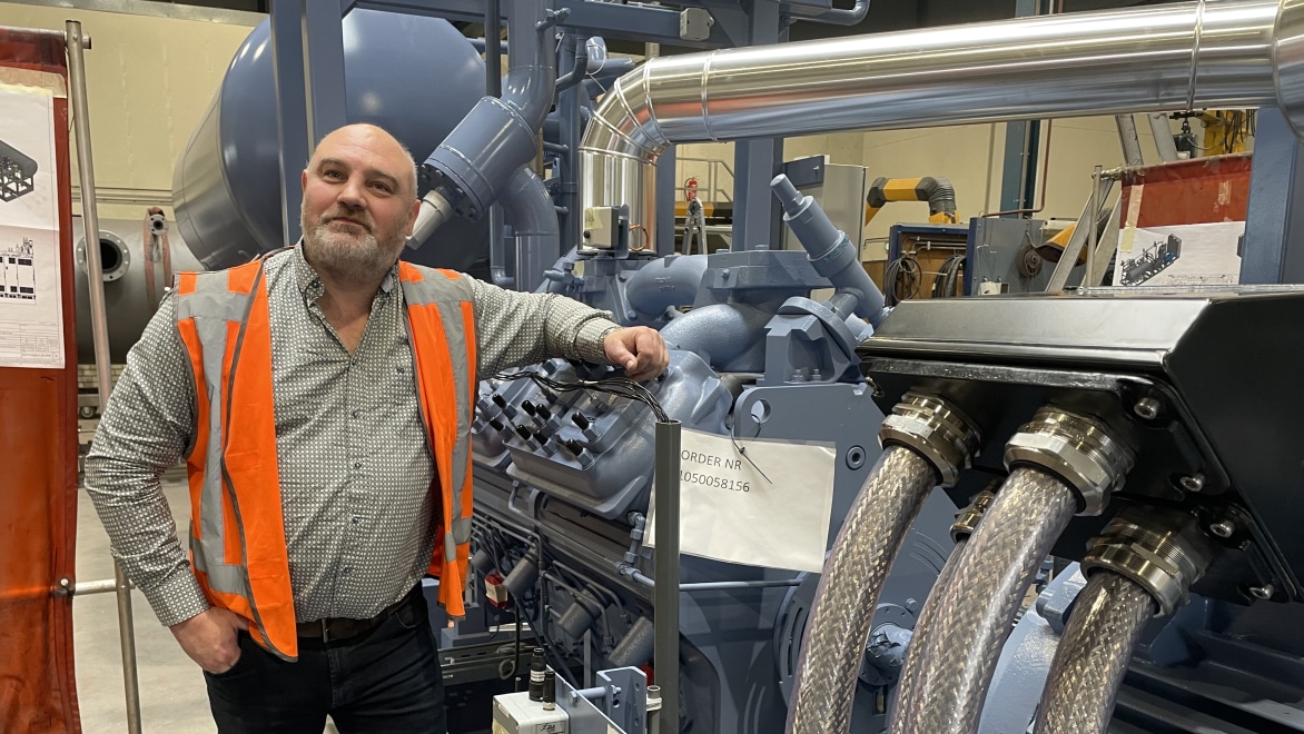
Lune Riezebos of GEA's OneEngineering team. Image courtesy of GEA.
Taking advantage of iLogic
To do this, GEA relies on iLogic, a specialized set of tools within Inventor that allows GEA engineers to capture and reuse certain components and assemblies through rules-driven design. Basically, iLogic provides a critical connection between the company’s custom systems and its standard offerings.
“We essentially create configurable models for our internal teams, which makes their workflow easier,” says Dutt Thakar, Senior Design Engineer. “It saves a great deal of time because they don’t have to repetitively create models from scratch.”
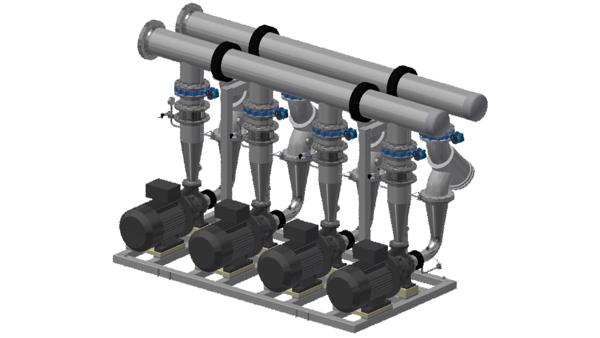
Water pump created by GEA's OneEngineering team. Image courtesy of GEA.
Streamlining customization
As you can imagine, large-scale processing systems use many of the same types of components—compressors, pumps, valves, controllers, mixers, homogenizers—in unique configurations. The iLogic tools allow Suthar and other engineers to create a “parametric skeleton” that standard product teams can adjust to create new models automatically.
“We meet regularly with the experts who understand all the intricacies of a specific process and the GEA machine for that process,” Riezebos says. “They explain what parameters they have, and that’s all we need to build a model that they can adjust and turn into many different configurations automatically.”
Over time, this creates a library of components that can be repurposed many times over, developing standardized products for custom scenarios without going through the full customization process.
“One of the best parts of model enhancement is making a standardized machine automatically when there wasn’t a standardized approach previously,” says Bhavik Suthar, Senior Design Engineer. “We create models in Inventor with iLogic in such a way that we can standardize it, whatever the components are.”
Faster results, unintended consequences
“We’ve shown our internal departments that they can create a new model in 2 hours instead of 3 weeks,” Riezebos says. “Depending on the complexity of the system, they can cut engineering time anywhere from 30% to 80%. That makes it much easier to meet customers’ needs.”
But the company soon realized its new approach had created an unexpected challenge during the sales process.
The sales cycle for very large processing systems can be long and intense because the customer and GEA are often figuring out how to perform a new task, make a new product, or solve a new problem. At the same time, GEA must use its engineering resources wisely, so it was not feasible to develop a complete 3D model of a solution before the customer signed the contract.
GEA had been bridging this gap by empowering sales teams to develop 2D layouts with AutoCAD® during the initial phase of the sales cycle, then recreating these layouts in 3D with Inventor after the sale was confirmed. Eventually, after the 3D version was finalized, the design would be added to GEA’s ERP system for production and delivery.
While it got the job done, this resulted in a great deal of duplicated effort, so the engineering team was eager to find a different approach. In addition, some uncomfortable situations arose when 2D system layouts that could not be manufactured as specified were inadvertently created. This was an unanticipated result of well-intentioned sales teams responding to customer requests for changes before the engineering team became involved.
“We had worked out a way for the sales teams to build systems by putting together ‘blocks’ in AutoCAD,” says Martin Andersen, Senior Manager Design Engineer for GEA. “But it was too easy to change aspects that shouldn’t be changed. When we reached the project phase and began redrawing everything from scratch, we had to tell the customers that what they signed off on could not actually be done.”
While Andersen’s team could always amend the 3D layout to meet the customer’s needs, the disconnect brought unnecessary friction into the process. At first the team looked to improve their efficiency with iLogic. But soon, they realized Factory Design Utilities was the solution.
Creating 2D and 3D layouts simultaneously
“I support Autodesk Inventor and Autodesk Vault across our organization, which means developing standards for how we use these applications and doing training,” Riezebos says. “But another part of the job is checking out new functionality within Inventor and seeing how it could be useful. One of these functions was Factory Design Utilities, which effectively links AutoCAD and Inventor, meaning we could create a 2D layout and a 3D layout simultaneously.”
The key point is that 2D and 3D models linked by Factory Design Utilities remain in sync, so any change made to the 2D model in AutoCAD will update the 3D Inventor model and vice versa. In addition, Factory Design Utilities is included with the Product Design & Manufacturing Collection, so GEA already had access to this capability. After testing the 2D layout to 3D model workflow, Riezebos and Andersen realized how valuable it would be for the entire engineering team.
“I support Autodesk Inventor and Autodesk Vault across our organization, which means developing standards for how we use these applications and doing training. But another part of the job is checking out new functionality within Inventor and seeing how it could be useful. One of these functions was Factory Design Utilities (FDU), which effectively links AutoCAD and Inventor, meaning we could create a 2D layout and a 3D layout simultaneously.”
—Lune Riezebos, Business Application Consultant for CAD, GEA
From weeks to hours
“When Lune showed me how Factory Design Utilities allowed us to go from 2D to 3D automatically, I couldn’t stop smiling,” Andersen says. “Because that was exactly what I wanted. Here we were recreating all of our sales drawings in 3D, and it was not necessary. We can just use Factory Design Utilities to go directly from 2D to 3D. And we’ve used it on all of our projects ever since.”
What this means from a practical standpoint is that the sales team is no longer responsible for creating 2D system layouts that are then later recreated in 3D. Instead, engineering takes direction from sales to create the initial 2D layout that is used to gauge customer interest. Because the 2D work can be transformed to 3D automatically, no time is lost in the process.
“In the first phase of the sale, if the 2D drawing is enough to make the customer curious then we can immediately move to the next step,” Andersen says. “Which means we go in and show everything in a 3D walkthrough at the second meeting, which sales appreciates. And by using Factory Design Utilities, we are saving so much time. For example, we can now create one of our systems in 2 hours instead of 3 to 4 weeks. It’s a huge win for us.”
“In the first phase of the sale, if the 2D drawing is enough to make the customer curious then we can immediately move to the next step. Which means we go in and show everything in a 3D walkthrough at the second meeting, which sales appreciates. And by using FDU, we are saving so much time. For example, we can now create one of our systems in two hours instead of three to four weeks. It’s a huge win for us.”
—Martin Andersen, Senior Manager Design Engineer, GEA

Martin Andersen and Dutt Thakar, Senior Design Engineers at GEA. Image courtesy of GEA.
Why showing is better than telling
By creating layouts in Factory Design Utilities, GEA has reduced the time involved by 80% compared to the previous workflow. Users can create a system layout in 2D or 3D and the outcome is identical, and the intuitive operation of Factory Design Utilities ensures an easy transition whether the user’s original preference is AutoCAD or Inventor. Moving the final layout into the ERP system is also much faster, due to the way the assets in the layout are composed and connected.
As an added bonus, GEA has eliminated the risk of customers signing off on system layouts that are not executable in real life, and can create more detailed, aesthetically pleasing layouts in less time. This not only minimizes the chance of later rework, but it also makes the entire sales cycle smoother.
“Our sales department wants us there at the customer meetings now. We do a 3D walkthrough of the entire plant. And that saves us a lot of time, because when customers are looking at a 2D drawing they often can’t visualize the final result. But now we can quickly provide the full 3D version, explain our design choices, and show them how it all fits together rather than telling them.”
—Martin Andersen, Senior Manager Design Engineer, GEA
Partnering with sales
“Our sales department wants us there at the customer meetings now,” Andersen says. “We do a 3D walkthrough of the entire plant. And that saves us a lot of time, because when customers are looking at a 2D drawing they often can’t visualize the final result. But now we can quickly provide the full 3D version, explain our design choices, and show them how it all fits together rather than telling them.”
In other words, several iterations of back and forth can be completed during a single walkthrough because customers can ask more informed questions and explore more potential options with GEA engineers in real time.
“We often get more insights into what the customer really wants instead of just the equipment they’re asking for,” Andersen says. “They tell us more about their business goals. The 3D model also makes it easier for our customers to sell the system internally to executives, because we can provide a shared Navisworks file that they can walk through themselves.”
Get started with the collection
Automation tools offered in the Product Design & Manufacturing Collection are designed to be a scalable solution that matures as you reach your goals. Products in the collection can help to define rules that drive custom product configurators, drawing creation, toolpaths, simulation setup, and more.