
P&ID stands for Piping and Instrumentation Diagram and utilizes a standard set of symbols to illustrate process systems flow for design, development, and operation.

What is P&ID?
P&ID, or a Piping and Instrumentation Diagram, is a detailed drawing or schematic primarily utilized in the industrial process industry to illustrate the interconnection between piping, equipment and the instrumentation devices used to control plant processes.
What is P&ID used for?
P&IDs are used to help design the layout of engineering process systems. The graphical diagrams include important information for installation or the systems included and provide detailed specifications outlining operational schemes and procedures.P&IDs are also used for systems modification and maintenance.
P&ID in AutoCAD
Learn the workflow of how to design a P&ID drawing with Plant 3D.
Discover the main International Standards for P&ID drawings.
Dive into documentation, tutorials, videos, and troubleshooting resources.
P&ID software

Software for 2D and 3D CAD. Subscription includes AutoCAD, specialized toolsets, and apps.
See how people are using Plant 3D toolset

PROCESS PIPELINE SERVICES
Elevating designs with 3D modeling
The Plant 3D toolset in AutoCAD helps oil and gas engineering and consulting firm to spot conflicts, manage site plans, and reduce turnaround time.
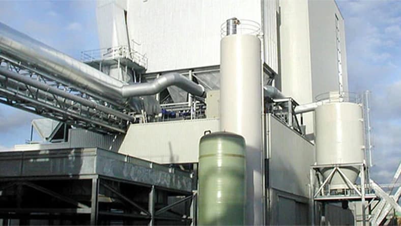
AALBORG ENERGIE TECHNIK
Designing biomass plants faster with BIM
AET uses BIM to develop biomass plants that generate environmentally-friendly energy using wood chips, corn stalks, and even chicken droppings.

HUNZIKER BETATECH AG
Modernizing aged water infrastructure with BIM Workflows
The engineering firm was tasked with combining two aged wastewater treatment plants at one location. A task that could only be accomplished using BIM.
Benefits of the Plant 3D toolset
An AutoCAD productivity study
See how the Plant 3D toolset provided up to 74% overall productivity gain* when compared to basic AutoCAD.
FAQs on P&ID
Learn more about P&ID software with these commonly asked questions.
P&IDs are typically developed by process design engineers for industrial processes (physical, electrical, or mechanical) for product manufacturing. Piping and instrumentation engineers follow the schematics to plan and develop plant build-out and coordinate with construction teams for installation. Process operators will also use the P&ID schematics for safety, training and operation.
P&IDs are typically developed by process design engineers for industrial processes (physical, electrical, or mechanical) for product manufacturing. Piping and instrumentation engineers follow the schematics to plan and develop plant build-out and coordinate with construction teams for installation. Process operators will also use the P&ID schematics for safety, training and operation. Yes, AutoCAD includes the Plant 3D toolset using industry-standard symbol libraries, drafting tools for quick P&ID schematics, and data validation to help identify potential errors in the design. AutoCAD also includes 3D modeling features to create rapid plant modeling in 3D.
AutoCAD Plant 3D is a toolset that is included with AutoCAD and is used to create and edit both P&ID and 3D plant models.
Yes, all subscriptions of AutoCAD include the Plant 3D toolset. Learn more about Plant 3D toolset features.
AutoCAD Plant 3D is included with your AutoCAD subscription. If you have infrequent users and are interested in a pay-as-you-go option, learn more about flex options.
A PFD is a process flow diagram which is a more general illustration of plant process flow between the major equipment in a plant. A P&ID is a more detailed schematic to show all the equipment, piping, instrumentation, and connections at a plant.
A P&ID typically includes the following components:
- Mechanical equipment and machinery
- Lines and process piping
- Piping fitting specifications
- Other piping requirements (slope, special insulation, distance requirements, etc)
- Manual and automated piping valves
- Safety Values Drains and vents
- Instruments and control devices Interconnections (OPC)
- Notes and additional information
All of the major industry-standard symbol libraries are available in Plant 3D including PIP, ISA, ISO/DIN, and JIS. Learn more.
See more FAQ
See less FAQ